(Click image to enlarge)
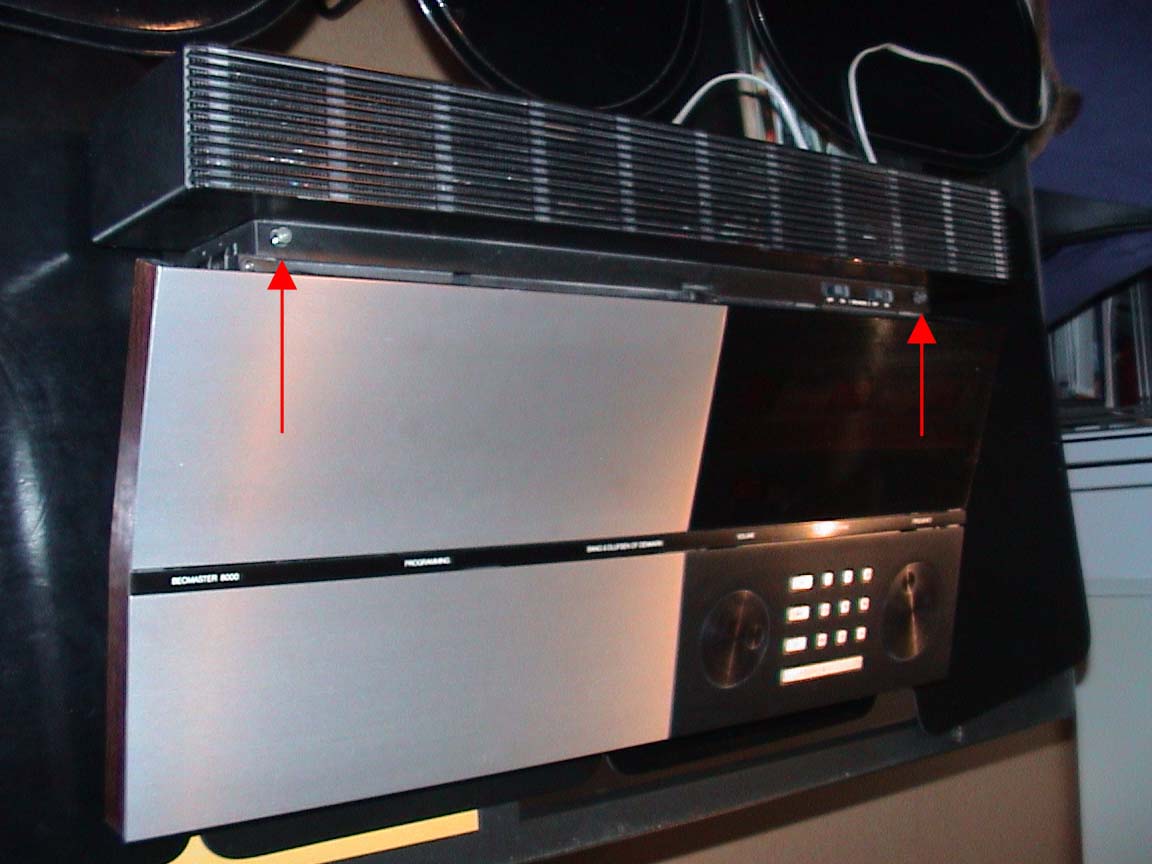
Have a number of little bowls ready to hold the screws you unscrewed, and put a little note in the bowl telling what stage of disassembly they belong to. This will help when re-assembling your Beomaster.
First loosen the screws as indicated here.
(Click image to enlarge)
You can now remove the plastic strip that was held by the screws. Remove it by lifting the back of the strip first. It will struggle a bit, but so can you. You are not intimidated by a plastic strip, are you?
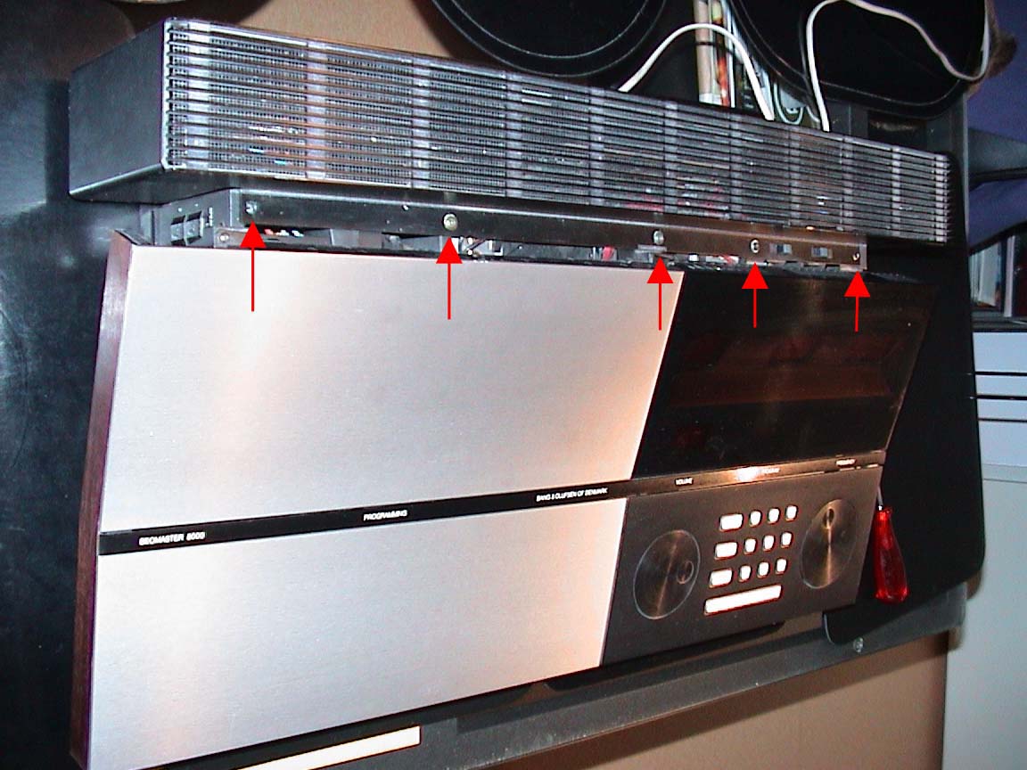
Now you will remove the black casing around the heat sinks, at the back of the apparatus.
First loosen the screws as indicated here.
(Click image to enlarge)
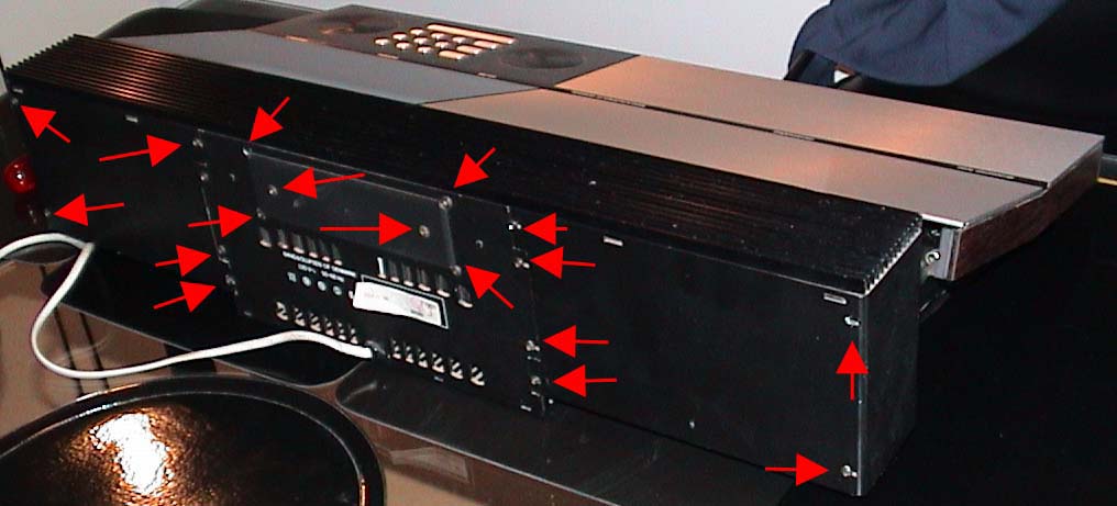
Now, at the back remove ALL screws.
(Click image to enlarge)
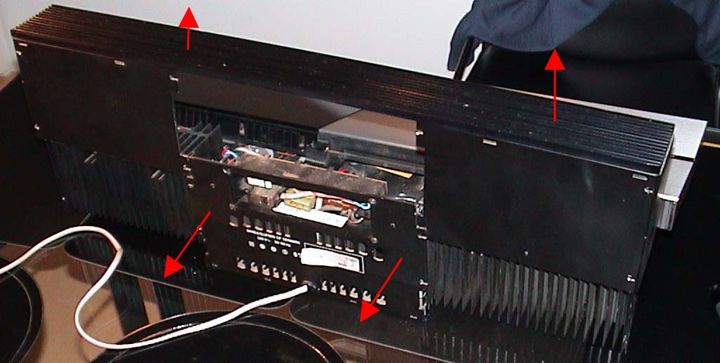
Gently pull the middle bit with the power cord outward (not by the power cord),
just a bit, you can now lift the casing of the heat sinks upward and off. Be careful not to pull
the middle bit too far, just enough so the heat sink can pass.
(Click image to enlarge)
The control electronics are located at the right of the machine, under the dark red
display. To access the electronics you need to further disassemble your Beomaster.
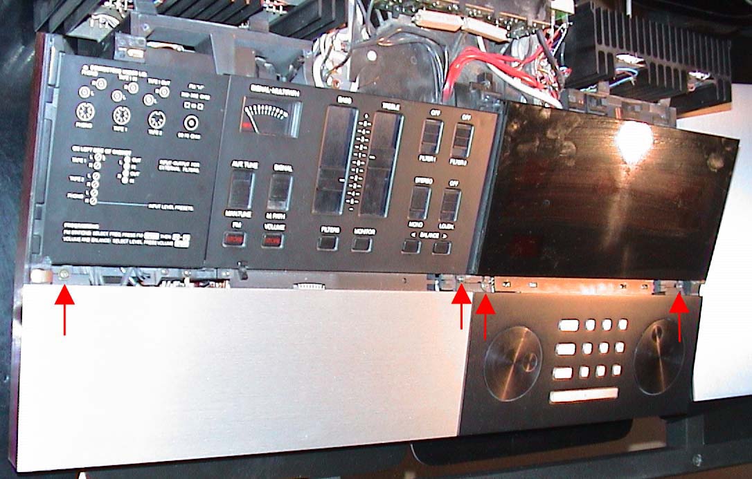
First you remove the aluminium cover of the controls (left side of the beomaster,
right side in the picture).
The cover is hinged at the left and right,
and it's movement is dampened with a damper, in the middle.
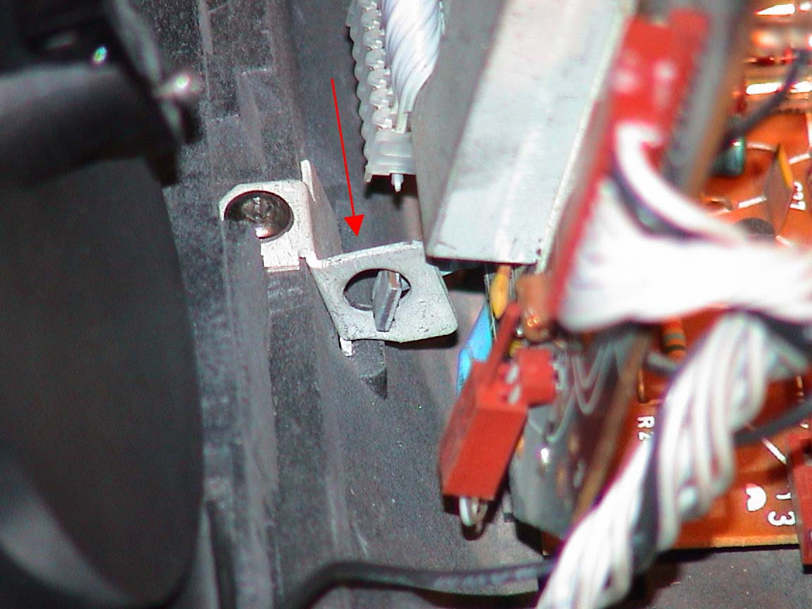
First you loosen the screws that hold the little metal plates, which in turn hold the
hinges. Remove the plates. You can now gently lift the back of the aluminium cover,
gently pulling the spring of each hinge from it's hole. It will go "pling", but not to worry.

(Click image to enlarge)
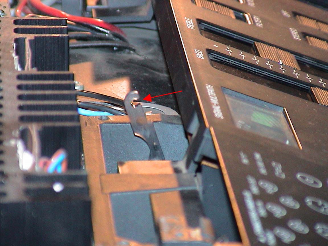
Now the cover is still hooked by the damper in the middle.
Hold the cover horizontally and unhook the damper,
by gently lifting the aluminium cover a little bit. Now you can pull back
the hook that is clicked onto a little bar in the cover a bit. It's
grip is quite strong, but if you press the hook backward you
should be ok. Look at the picture for the shape of the hook
to determine how you should un-click it. Do not force things here,
or twist the aluminium cover. The damper is made of plastic, now more
than 15 years old, and probably not easy to replace.
(Click image to enlarge)
The next task is to remove the black bar labelled "beomaster8000",
"programming" etc. You remove it by pressing it down everywhere,
using your third and fourth hands. By sliding it to the LEFT at the
same time you unhook it. You can now lift it from it's slot. Be careful
lifting it out, it's sharp, and aluminium and red perspex scratch easily.
Under the bar are more screws to loosen (and not lose):
(Click image to enlarge)
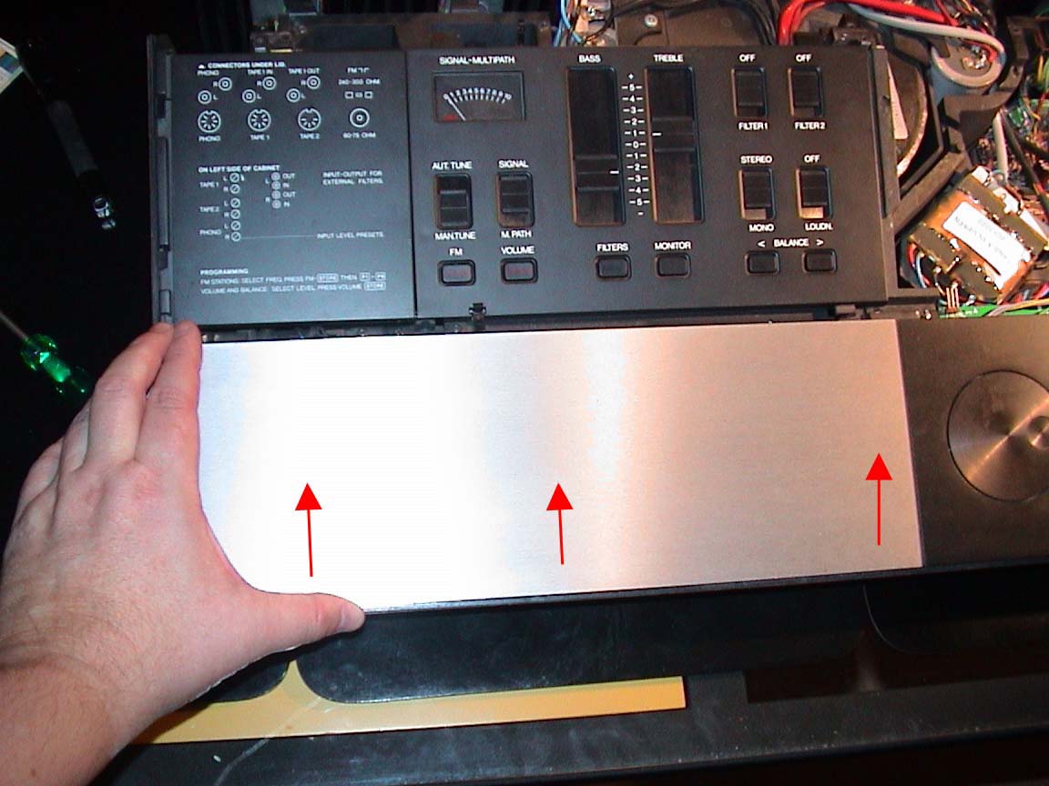
Now we are opening up the lower part of the beomaster.
Place your left hand as indicated in the picture, and your right hand
at the right, with your thumbs pushing the strip with the volume
and tuning controls towards the back of the beomaster.
Make sure
you press evenly at the left and right, while keeping the beomaster
in place with your fingers. The strip will click and slide up, narrowing
the slot where the black bar was. Stop pressing if it's loose, after just
a few millimeters.
(Click image to enlarge)
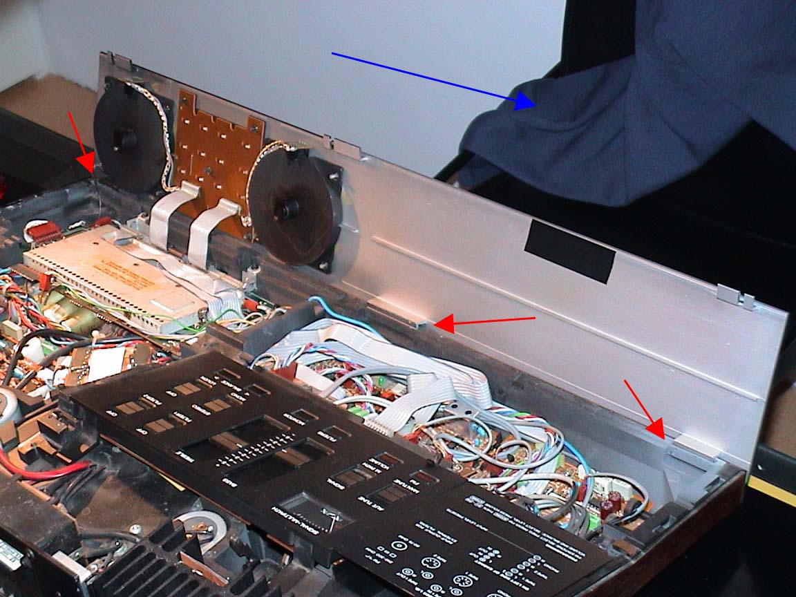
Here comes a clever bit in the beomaster design, one of the few
that is nice to the service technician: you can now put the strip in
an upright position, and hook it in slots in the front of the casing, so it stays
upright. Mind, the picture is taken from the back of the Beomaster.
The blue thing is the sweat shirt that has now come off too. Opening
up a beloved Beomaster is nerve wrecking work, a sweat shirt just makes you do
just that. Odd, you'd think sweat shirts were made for sweating, instead
they make you sweat.
(Click image to enlarge)
What to do now depends on what you need to access. I needed access to
the power supply of the control section. This is located under the control
board, the one with the metal box. The box is labeled "do not open,
return to distributor for maintenance". Very tempting, but better control yourself.
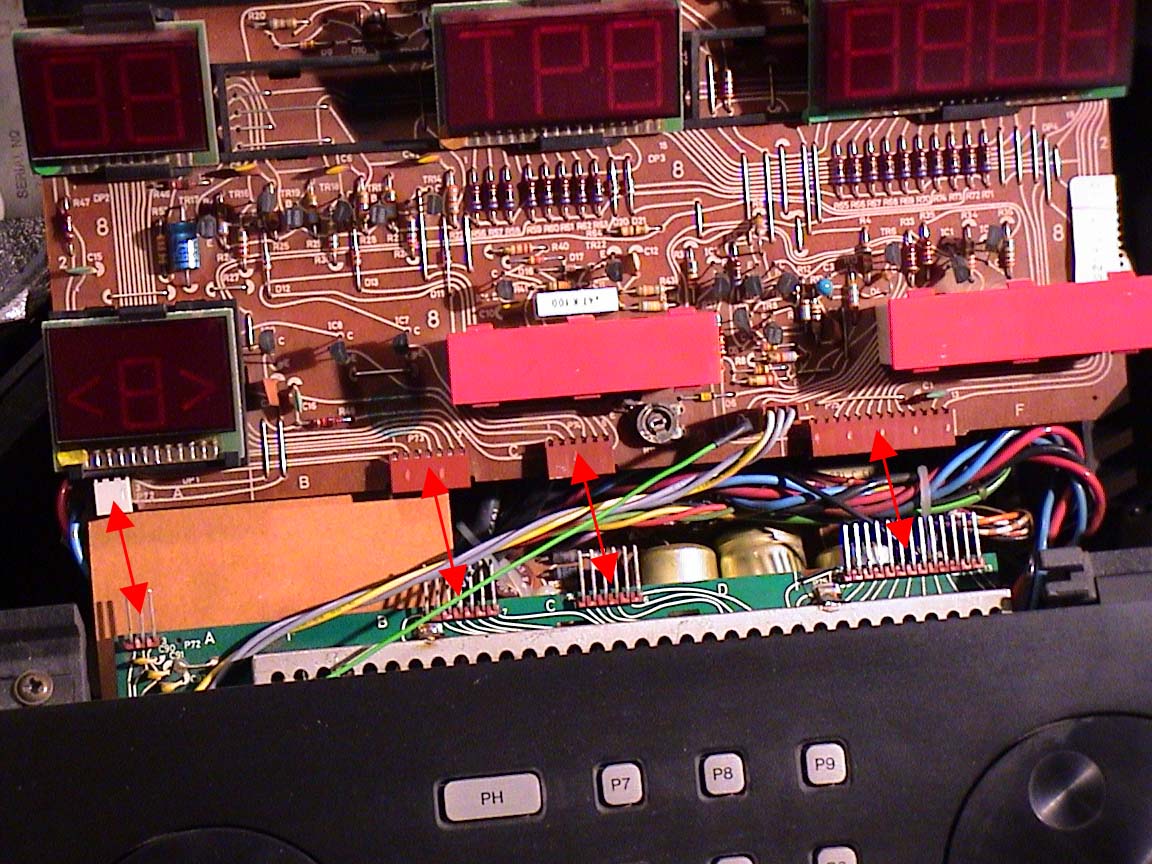
The display board (upper) and the
control board (lower) are connected with a few connectors:
(Click image to enlarge)
You can separate the two prints, but it is easier to simply lift both
prints together. Be careful, support the two-print-assembly
in the middle where they are connected, else you'll damage the connectors!
They are hinged at the bottom, and will stay
upright because of clever hinges:
(Click image to enlarge)
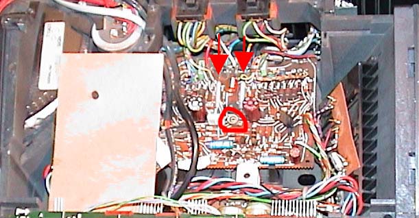
The print at the top is the right pre-amplifier, the one below that is the low-power supply for powering the tuner, controls and lights. Under the brown piece of carton is the transformer for that low-power supply. (The actual power amplifier is fed with a huge ring transformer, which is hidden in a big metal can, in the back in the middle. Can't miss it. (Can you guess now why the Beomaster 8000 weighs 15 kilos?)
The Beomaster has separate amplifiers for both channels, one is located
at the far left, the other at the far right of the machine.
There are two power resistors that are mounted a bit above the print.
I measured the voltage across them, and compared to the values of the left
amplifier. Indeed the voltage across one of the resistors was different.
By adjusting the potmeter the voltage was made equal to the voltage in the
other amplifier. I guess the potmeter had corroded or something. I haven't
replaced the potmeter (it's a cermet type, by the way, nice), this is now
four years ago, and it remained good so far.
(Click image to enlarge)
I measured the voltages at
the terminals of the big elco's. They were, from left to right:
+24.1V, -24.9V, +10.72V at the elco's,
There are also 3 power resistors on the board,
the voltage at their terminals was:
+22.7V, -23.5V, -5.7V at the power resistors.
I have no service manual, so I'm not sure what the voltages are supposed
to be exactly. I replaced all three elco's (2x2200uF/40V, 1x4700uF/16V)
by the same values, but higher voltage, just to be safe. The voltages have
now changed:
+24.7V, -25.6V, +11.25V at the elco's,
+23.3V, -24.1V, -5.75V at the power resistors.
So far the problem has not re-occurred, fingers crossed.
Rick Jansen